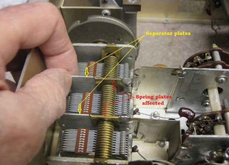
Service Note 006 Instability and anomalies caused by the Pre-selector capacitor used in the Hallicrafters SR-2000 and SR-400 series Transceivers. The symptom, cause, and fix: The primary symptom: Occurs when the pre-selector is peaked in transmit mode. The output and plate current swing erratically and at times the finals seemed to self oscillate; even when the capacitor was left stationary. THE 12BY7A WAS OSCILLATING NOT THE THE FINALS. In receive mode it may sound scratchy when you turn the pre-selector. First, test to verify the rotor and stator plates are not touching: Set up your capacitor tester in leakage test mode for small capacitors i.e. mica. Use the tester as a Hi-Pot device. Disconnect the lead to each stator. Apply voltage for the leakage test beginning at 50 volts while swinging the capacitor from end to end, watching for leakage. Continue to 500 volts. The capacitor will weather 500 volts even though the plates look to be shorted. Remember, arc distances are not linear. A gap of only a few thousandths of an inch will need 300 volts to jump. If it passes the Hi-Pot test to 400 volts, the problem is in the grounding. The pre-selector caps in the SR-2000 and SR-400 will easily pass the 600 volt test. If they are not touching the likely problem follows: The separator plates have lost their shielding properties and are allowing feed back from the driver gang to the pre-driver gang creating a feedback loop. Attaching your ohm meter to the separator plate and capacitor frame measures zero ohms. It will always be zero ohms because the capacitor is screwed to the chassis and so too, is the separator plate. The separator plates require a second ground that is provided by the spring plates to rotor. Without the second ground the shielding effect is seriously compromised. The separator plates are grounded to the rotor axle by Phosphor bronze spring plates that are soldered to the separator plates and spring loaded to the rotor axle. This ground connection is essential even though they are connected through the chassis. The second ground is a requirement when adjacent gangs are used for adjacent input and output tuned circuits or oscillators --- on any radio. The separator plate is extraordinarily flexible and will bend easily resulting in the flattening of the spring plates over time. The Fix: Clean the spring plates including the area under the plate with Deoxit D100; it leaves no residue. Slip a small silver plate under the spring and solder it to the separator plate. This will add pressure to the spring plate and reduce the gap. If you need a silver plate, remove a contact from a rotary switch and form it under the spring plate, soldering it to the separator plate. NOTE: Hallicrafters service note 12/29/1969 written by F. Daniel was expected to fix this problem but it continued to fail in some radios even after it was installed. The fix was to add a ground lug at the other end of the Mu metal plate that shields the 12BY7A input and output. The Hallicrafters fix helped but altering the spring plates as described above is the permanent fix. Kindest regards Jim K9AXN |