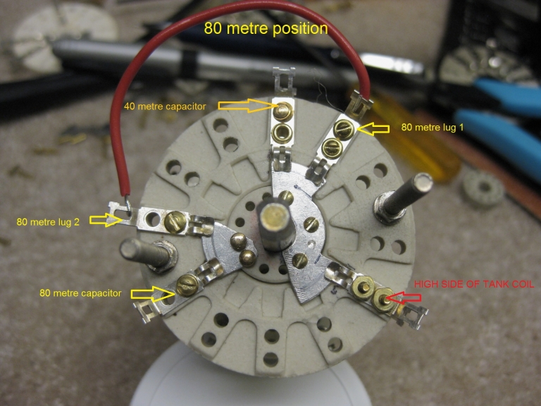
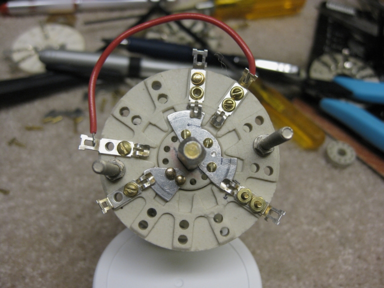
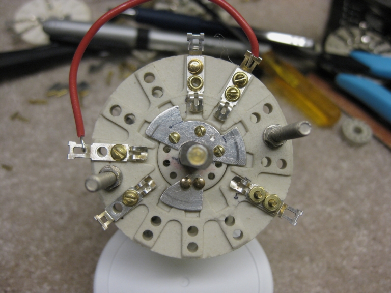
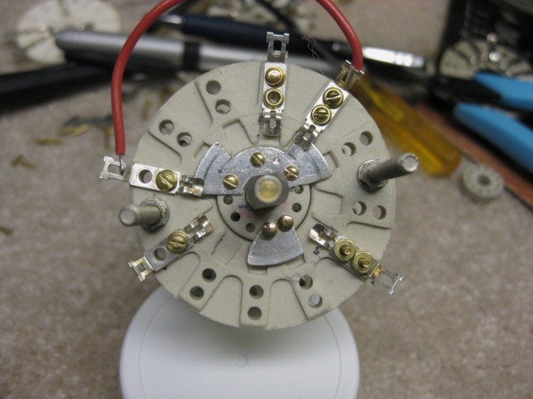
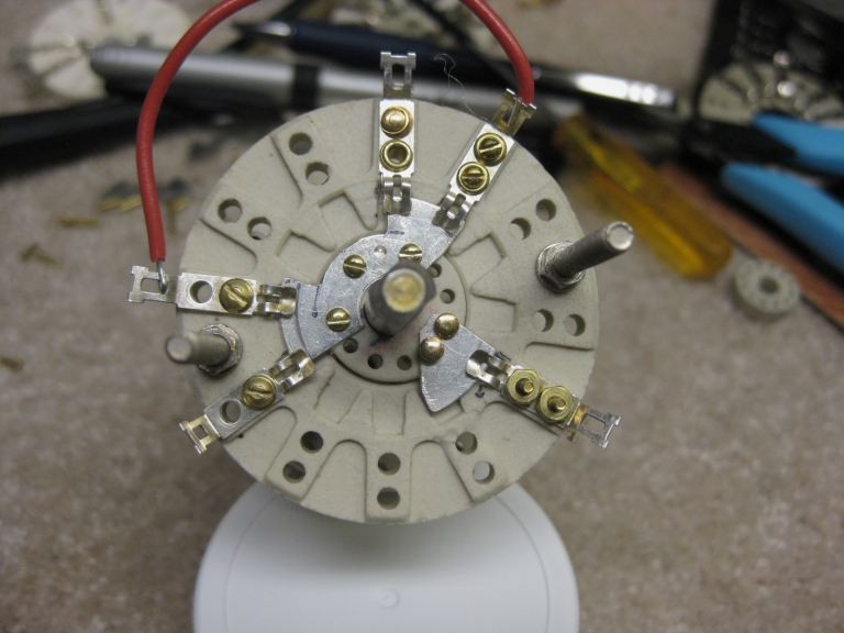
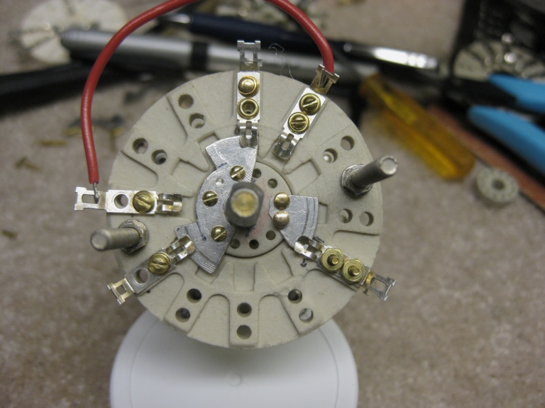
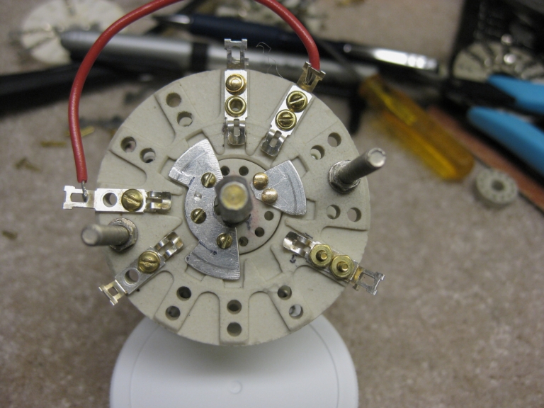
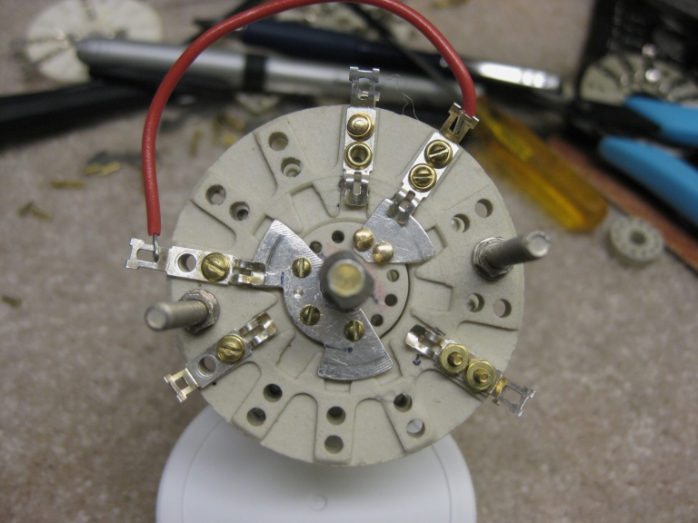
The following switch configuration represents a doubling of the arc gap for both the 80 and 40 Metre bands. Most if not all of the amplifiers produced in the same era had but 1/2 the gap that this switch has with one exception the 1971 switch version used in the SR-2000. It had four gaps which were used by integrating both the 80 and 40 bands and simply changing the 40 Metre final tuning resonant point from the 50 dial position to the 70 point. This way, all of the available gap configurations could be used multiplying the arc gap. This same configuration can be used for the NCL-2000 providing a double gap for both the 80 and 40 Metre bands. The band switch used in the NCL-2000 and most other amplifiers use a single gap switch for this function. Hallicrafters used the same single gap design in the pre-release SR-2000 finding it to arc and fail at a line voltage of 124 volts and lightly loaded finals. It was changed to a double gap 20 Meter and single gap 40 Meter switch configuration before release and soon began to fail on the 40 meter band because there was only one gap on 40. At that point the 80 and 40 Meter bands were shorted together with the double gap 20 Metre remaining. There were intermittent failures for the next few years so they altered the switch for the last time in 1971 to a 4 gap configuration by using a double on each side of the wafer. This reduced the current carrying capacity to 9 amps but was within the design limits of the output requirements. The following series of photos will illustrate the switch positions 80, 40, 20, 15, 10-1, 10-2, 10-3, and 10-4 positions for the SR-2000. All of the 80 Metre components, the three contacts, and left rotor plate are unnecessary for the SR-2000 because the 80 and 40 meter positions have been combined. The first 5 positions and 80 Metre components would be used for the NCL-2000 because it does not switch through 500Kc 10 Metre segments like the SR-2000 and the 80 and 40 Metre positions are still separate. I believe it makes a great deal of sense to combine the 80 and 40 Metre positions as done in the SR-2000. The only change would be to short the two contacts together and resonate the 40 Meter final tuning capacitor a bit higher. The change when installed on the SR-2000 simply moved the resonant knob position from the 50 to 70 dial setting and there was no design denigration. |