SX-115 Filter Photos
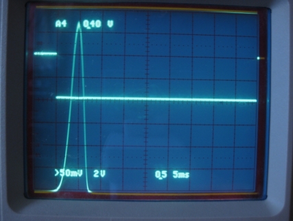
.5Kc position
Changed one of the 2.2pf top coupling capacitors to a Class 1 NPO Ceramic plate capacitor. The Q of the old cap was 200 and the new cap 2000. Improved the 1Kc to .5Kc loss.
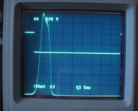
Correct 1Kc wave form
Polypropylene capacitors
Measured after warm up in a room set to 72 or 82 degrees.
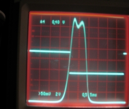
Sweep of the 1Kc POSITION before changing the CERAMIC Z5U capacitors to Polypropylene.
Measured after warm up in a 72 degree room.
The photo to the left represents the correct 1Kc band pass using Polypropylene caps.
The total capacity of the two .01uf, and .0047uf capacitors was .0162uf. Should have been .0247uf.
Notice the band width is almost as wide as the 2Kc position before changing the ceramic caps to Polypropylene.
The photo is a result of the reduced capacity of the old capacitors causing the k to increase expanding the band width to 1.9Kc and the dip in the center is because the 1Kc position does not use Q reduction resistors. The circuit is significantly over coupled.
Except for the 1Kc position the Q must be reduced as the coupling is increased to accommodate the fixed load.
Conclusion: The ceramic capacitors have shifted and expanded the 1Kc band pass to nearly 2Kc and had similar effects on the other band widths.
Changing the ceramic Z5U capacitors to Polypropylene results in the correct sweep patterns.
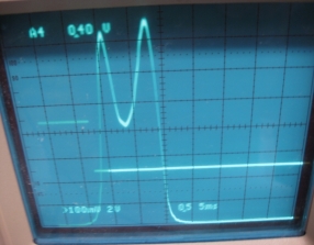
Sweep of 1Kc position before changing the Ceramic Z5U capacitors to Polypropylene.
Measured after warm up in an 82 degree room. Note the severe over coupling as a result of the reduction of capacity caused by the 72 to 82 degree change in room temperature.
The sweep shapes of the Polypropylene caps are unaffected by the 72 or 82 degree room temperature.
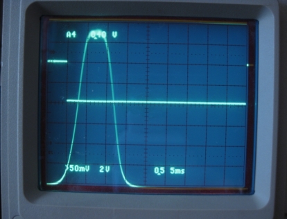
2Kc position Polypropylene caps
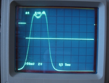
3Kc position Polypropylene capacitors.
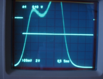
5Kc position Polypropylene caps.
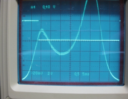
Sweep of the 5Kc position using ceramic Z5U caps before changing to Polypropylene.
Note: There are two peaks with a severe dip in the center caused by over coupling. Note: It is approximately 6.4Kc wide.
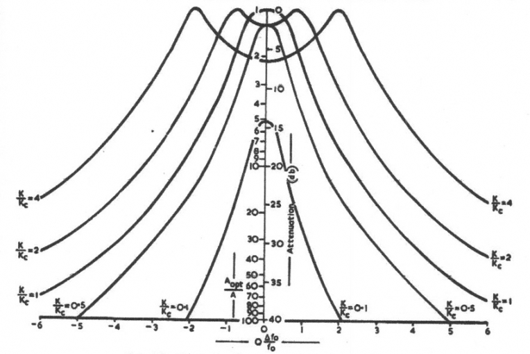
FILTER INFORMATION
The 50Kc filter used in the Hallicrafters radios are essentially quite the same. The following information will describe the function in detail using logic and language. Math will be used only to support the content.
The accompanying chart and a to be added narrative and circuit drawing will be used to define the concepts.