Neutralizing Concepts Part 1
ABOUT NEUTRALIZATION:
Why is neutralization necessary in a vacuum tube amplifier? The capacity between the plate and control grid has two primary effects that are disruptive for linearity and stability.
FIRST:
It causes negative feedback at the operating frequency which has a degenerative effect on the drive to the grid. In the absence of neutralization the drive must be increased to achieved full output. This feedback does not affect efficiency; it simply requires more drive.
SECOND:
It is positive feedback to the parasitic Hartley circuit formed just below the operating frequency which occurs naturally in all tuned grid/tuned plate vacuum tube amplifiers. This effect is insidious and must be neutralized. Video clip # 2 is a good example of a seriously under-neutralized amplifier. You will see two things occur. The grid voltage will be aggressively muted as you tune the plate cap through resonance. Then, further tuning to a higher frequency the grid drive and plate voltage will increase with a peak that does not coincide with the plate dip. This peak is the point where the Hartley parasitic begins to form with the greatest risk to linearity and stability.
The common practice of tuning for peak output rather than plate dip places the radio at the highest risk for instability. Peak output occurs for two different reasons depending on the amount of neutralizing feedback.
If the PEAK OUTPUT occurs when the final tuning cap has to be adjusted to a higher frequency than the plate dip there is inadequate neutralizing feedback ---increase the neutralizing cap. This is caused by the Hartley effect which will be fully explained as we go.
If the PEAK OUTPUT occurs when the final tuning cap is adjusted to a lower frequency than the plate dip, there is too much neutralizing feedback. Decrease the neutralizing cap. Neutralizing feedback is regenerative and meant to counter the degenerative feedback from plate to grid at the operating frequency. Excessively high it will precipitate oscillation at the operating frequency like any other regenerative feedback.
SNIPPET #1: The reasons for each video clip will be fully explained as we move on.
Video clip #1 is a good example of a correctly neutralized amplifier. We use this to demonstrate the effect of final output on grid drive. This clip is a good example of the negative feedback that every designer seeks. The plate dip and peak output are exactly in sync along with mild negative feedback. This can only be accomplished when every band can be precisely neutralized. It won’work when 10 Metres is neutralized and the lower bands are swamped --- which is fairly common design practice.
SNIPPET #2:
The neutralizing cap is patently inadequate, causing the peak output to occur when you tune the final cap to a higher frequency. Just as you tune above resonance, the tank begins to look like an infinitely high inductance in parallel with the load resistance. The inductance will decrease rapidly as you tune further. At some point the inductance will intersect and resonate with the grid to plate capacity. It is at that point you see the plate voltage peak to the left of the grid signal. At this point oscillation or instability is most likely to occur. A full explanation of the effect will follow.
SNIPPET #3:
The neutralizing cap is excessive. This causes excessive regenerative feedback because there is more plate voltage fed to the bottom of the input tank than the top. Notice the grid voltage increases when the final tuning cap is rotated to a lower frequency. This causes the final tank to appear as a capacitor.
SNIPPET #4:
This setup simulates a disconnected antenna. It is extremely lightly loaded and properly neutralized. Note the natural plate to grid negative feedback is depressing the grid drive but not changing the phase. Also Note the control grid is going a bit unstable from a parasitic effect but is still safe. This an example of the parasitic suppressors working to dampen a parasitic oscillation and is a simple way to verify that the resistors in the parasitic suppressors are working.
SNIPPET #5:
This is a slightly over neutralized amplifier. Tuning the plate capacitor through resonance will have no effect on the grid voltage; if the tube is perfectly neutralized, the grid voltage will be slightly depressed.
This paper will focus on grid driven tuned in and out amplifiers. The intent is to fully explain the various attributes of grid driven amplifiers, then define the interactions that cause instability and damage to linearity.
The PLATE to CONTROL GRID capacity has a degenerative feedback effect, not regenerative on grid drive when both the input and output tuned circuits are resonant at the same frequency. It is common belief that an unneutralized TGTP amplifier will not oscillate unless the plate is tuned to a higher frequency than the grid. This is not correct; It is simply more likely to oscillate when tuned higher. This will be explained later.
Important concepts regarding parallel tuned circuits:
PARALLEL LC CIRCUIT:
Visualize a parallel LC circuit tuned to resonate at 14Mc with a 14MC signal applied to it with no resistance in the circuit. There is infinite resistance and no notable reactance.
If you tune the capacitor to a slightly higher frequency (Less capacity higher reactance) the circuit begins to exhibit immense inductive reactance, infinitely greater than the coil.
If you tune the capacitor to a slightly lower frequency (More capacity less reactance) the circuit begins to exhibit immense capacitive reactance again infinitely greater than capacitor.
TEST SETUP FOR EXPLANATIONS:
The following neutralizing technique is simple, precise, and quick to accomplish. It can be done with nearly any radio. The instrument used is a dual trace scope with probe 1 attached to the tube shield of the driver which is pulled up from ground. This non-disruptively measures the drive to the control grid of the final tubes. Probe 2 measures the high end electric field from the final tubes with the trace inverted in chop mode.
NOTE: The sense probe for the final output as you see is a common tip with the hook cut back and completely sealed and cast with corona dope. IT IS NOT PUSHED THROUGH THE COVER!! You can simply lay the probe over the final shield to acquire measurements.
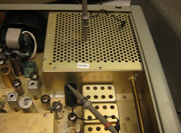
The upper trace in the following movie clips is the voltage on the control grid sensed by the probe attached to the driver tube shield and the lower trace the output voltage sensed by the probe over the final compartment and inverted.
Click on the following video clips to view the effect of neutralization.
#1: Correctly neutralized. Note the depression of the grid signal from negative feedback.
#4: Close to correct but very lightly loaded simulating no antenna connection.
#5: Seems perfectly neutral but over neutralized. Note the absence of negative feedback.
NEUTRALIZATION
Neutralizing a grid driven amplifier is required for two primary reasons. First to equalize the negative feedback across the input tuned circuit caused by the Plate to Grid capacity at the operating frequency. Second to equalize the Positive feedback caused by the P to G capacity at the natural Parasitic frequency just below the operating frequency.
Important point 1:
The plate to grid capacity is degenerative at the operating frequency and regenerative for the Parasitic circuit that naturally forms just below the operating frequency in Tuned grid Tuned plate amplifiers. The parasitic circuit is always present, and how it influences the operation of the amplifier can be predicted, calculated, and neutralized. The circuits below will demonstrate how the Parasitic is formed and how to deal with it. I call it a Parasitic because it falls within the unwanted category even though it is predictable and essentially absolute.
Important point 2:
The Bruene single ended neutralizing technique described below has some notable characteristics that need to be considered when designing amplifier circuits.
Multi band radios are generally neutralized for the 10 Meter band assuming the lower bands will follow --- but they don't follow as assumed. The LOWER bands using the 10 Metre components require less feedback, becoming progressively over neutralized. The neutralizing feedback is regenerative at the operating frequency. It is meant to balance the negative P to G capacity, but on the lower bands it becomes excessively regenerative.
There are several schools of thought regarding these issues. The issues will be addressed in a follow on paper (Part 2) that will focus on the 6146B issues and emerging design principals that surfaced when Sweep tubes became popular in the 60's. The 6146B was meant to compete with the sweep tube market.
NOTE: In a Tuned Grid Tuned plate amplifier there are 3 tuned resonant circuits: The input, The output, and one slightly below the operating frequency consisting of the grid to plate capacity and the combined inductance of the input and output tuned circuits just below the operating frequency.
The following schematics will explain why this circuit is naturally unstable unless measures are taken to neutralize it.
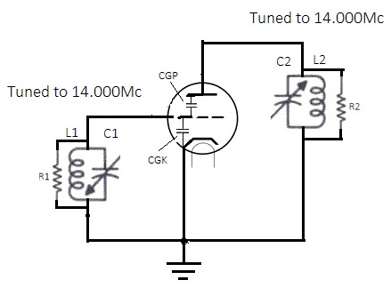
Fig1
The above schematic is a common amplifier circuit that has not been neutralized. Note the plate and CG are 180 degrees out of phase. This will result in negative --- degenerative feedback. Negative feedback infers stability but it's far from stable.
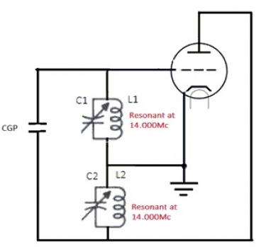
Fig2
This schematic is the same as the amplifier circuit in FIG 1 redrawn to make it easier to explain why and how it will be unstable and oscillate even though it appears to have degenerative feed back.
NOTE: CGP has been drawn external to the tube.
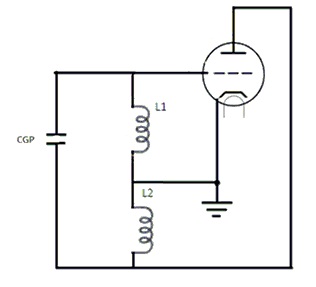
Fig3
This circuit is physically the same as Figure 2.
It represents the behavior at the parasitic frequency (The Hartley oscillator)
This configuration represents the parasitic frequency below 14.000Mc. At frequencies below 14.000Mc the input and output circuits behave like inductors. you will also note the plate to control grid capacity has been drawn outside of the tube for clarity.
The fundamental point to remember here is how the properties of a parallel resonant circuit change when subjected to frequencies below resonance. Just as you decrease the frequency the circuit changes from resistive to inductive beginning with an infinitely high inductive reactance hundreds + times higher than the coil itself. It continues to diminish rapidly as you reduce the frequency.
At the same time, the plate to control grid capacitive reactance increases at a linear rate when the frequency is reduced. The CGP capacitive reactance and inductive reactance of the tuned circuits will intersect reaching equality resonating just below 14.000Mc. At that point the circuit becomes a Hartley oscillator as you see above.
Swamping is a common technique used to quench oscillation in amplifiers. Swamping the input or output circuits in an amplifier corrects nothing except to make it a bit more difficult for the parasitic circuit to oscillate. Swamping (adding resistance) to an amplifier circuit to stabilize it is nothing more than a band aid. The amp will oscillate if the output or input load is removed if it's not neutralized.
Here is something to think about. Have you ever heard the lamentations about band switches arcing in just about every vintage amplifier. Problem is incorrect neutralization and disconnecting the load from the final tank. The loss of load in an amplifier that is not correctly neutralized will result in a high power oscillator.
Note video snip #4: That is an amplifier that is neutral and loaded as though there is no antenna. Carefully look at the grid waveform. You can see instability beginning to form but the parasitic suppressors are quenching the instability.
The chart below demonstrates the effect frequency has on a parallel tuned circuit. The peak reactance at resonance is purely resistive. Then as the APPLIED frequency is reduced it becomes extremely inductive. As the APPLIED frequency is increased it becomes extremely capacitively reactive . The chart below represents the effect.
The plate to grid capacitive reactance increases in a linear fashion, at the same time the inductive reactance decreases rapidly when the frequency is decreased. Where they intersect oscillation can occur if the Q's are high enough. Regardless, the circuit will have a propensity to oscillate even if quenched if it's not neutralized.
You can calculate the frequency where oscillation occurs and you can manipulate the degree of regenerative feed back by tuning the plate capacitor.
If there is a lack of clarity please let me know and I'll rewrite it best I can.
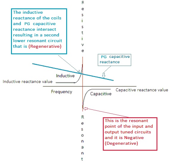
FIG 4
This chart represents the effect frequency has on a parallel tuned circuit.
Hope you found the first section interesting.
NOW TO NEUTRALIZE THE AMPLIFIER:
SEE FIG 5 BELOW:
There are two ratios (CGP/CGK) and (CNC/CGKn) that must be equal to neutralize this amplifier. Once they are equal the plate to grid capacity has the same effect on both ends of the grid coil. This neutralizing technique is single ended and is referred to as the Bruene method. CGKn is added to lift the coil from ground and CNC is the other half of the bridge.
CGKN is part of any single ended Bruene neutralizing bridge. It is fixed and used for all bands in some transmitters along with swamping resistors for the lower bands. Some radios use design selected equalizing capacitors (CGKn) for each band enabling precision neutralization for all bands. A few are designed with ADJUSTABLE CGKn capacitors for each band.
I know of only one engineer that designed a transmitter that could accommodate any tube in the 6146 family and attain precise neutralization on all bands through adjustments. Most others use a combination of fixed neutralization on 10 Metres and swamping for the lower bands --- fixed Neutralizing for all bands --- or Fixed neutralization for some bands with swamping.
NOTE: The anode to CGKn capacity can be used to affect negative feedback to improve linearity and IMD performance with the single ended neutralizing design. However, it occurs only on the bands that are precisely neutralized. This will be covered in depth in part 2 of the series.
For more detailed information regarding Beam power tetrodes see the service note #43
This url has some information that you might find interesting when looking for transmitting tubes.
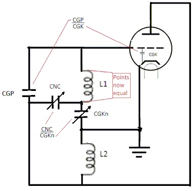
Fig 5.
NEUTRALIZED AMPLIFIER
CGKn is the equalizing capacitor added to the band switch for each band to enable precision neutralization. Without the individual capacitors the amplifier will not be precisely neutral on all bands. Part 2 of the series will explain why this is true.
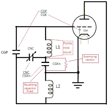
Fig 6.
Hybrid Neutralizing technique using the traditional bridge for 10 Metres and swamping resistor to equalize lower bands.
This neutralizing configuration is generally used in more current radios and is not considered precision neutralization. Many radios insert the swamping resistors across the L1 coils for the lower bands. The swamping resistor in Fig 6 is the best inexpensive solution because it provides incrementally increased swamping as the frequency decreases.
It precision neutralizes only the 10 Metre band and simply swamps/reduces the Q of the oscillator circuit making it more difficult to oscillate in the presence of excessive positive feed back in the lower bands.
Observations to think about:
A: No radio has to be perfectly neutral on every band. The designer chooses priorities i.e. linearity and risk to stability.
B: When a radio is neutralized for 10 Metres using the single ended neutralization (Bruene technique) the lower bands will become progressively over neutralized. Part 2 explains the reason.
C: A tube with more than .40pf PG will likely require each band to be equalized for linearity and stability.
D: The range of operating values of a beam power tetrode for bias are divided into four quadrants that historically were only available to designers Today the quadrants are publicly available only for the Burle 8122 tube. They are defined by color code Red, Blue, Green, and Black from lowest to highest bias. Not published, is the deviation in plate to grid capacity generally follows the idle bias level --- a high bias tube will have a higher PG capacity. All beam type tubes have the same behavior.
E: An under neutralized amplifier will require more drive than an amp that is properly neutralized.
F: An over neutralized amp will require less drive for full output.
G: Most designers use swamping to counter the over neutralizing effect on the lower bands.
H: Sweep tubes universally need equalization on some or all of the lower bands because they have far higher P to G capacity than a 6146.
NEUTRALIZING CONCEPTS PART 2 IS NOW AVAILABLE
If you find any unclear points please send a note to me at hallicrafterssr2000@k9axn.com
Edited for clarity 3/29/2017 and 6/28/2017