National NCL-2000 and SR-2000 Band Switch Evolution 067A
National NCL-2000 Band switch.
Same configuration as the SR-2000 Beta switch.
This configuration is doomed to fail very quickly.
NOTE: THE FRONT WAFER FOR THE NCX-1000 HAS BEEN REDESIGNED TO PROVIDE A DOUBLE GAP. THE NCL-2000 WAS NEVER CORRECTED. STILL HAS A SINGLE GAP SWITCH. EASY FIX FOLLOWS.
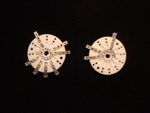
SR-2000 Beta band switch same as NCL-2000 switch.
Almost all failed within weeks. Never used in production. Same configuration as NCL-2000 switch.
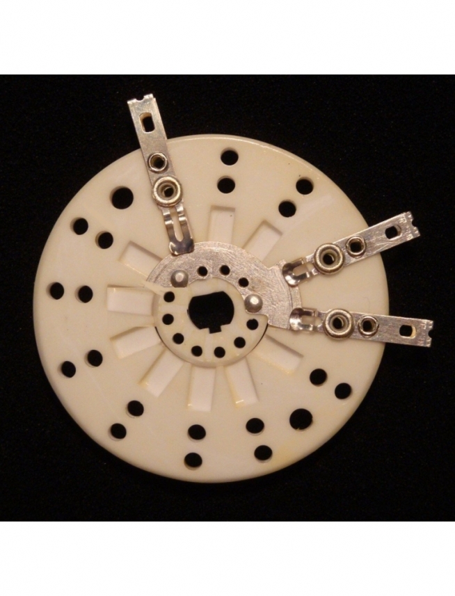
This is a correctly configured NCL-2000 band switch.
This is a photo of a correctly configured NCL-2000 front wafer. Notice the wafer rotation has been reversed compared to the photo above; enabling an additional gap.
Trim the rotor plate and move it around the spindle until it looks like this photo when the switch is in the 80 Metre position.
The switch is in the logical 80 Metre position. Rotate it clockwise to the 20 Metre position noting the extra gap now present doubling the corona gap. In this photo the rotor plate has not yet been rotated on the spindle when the switch is in the 80 Metre position.
Make your switch look like the following link when in the 20 Metre position.
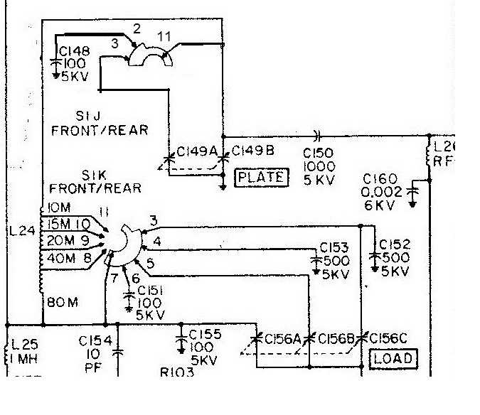
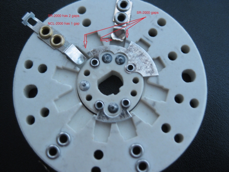
SR-2000 A level first production band switch..
This configuration did not fail on 20 metres but continued to fail on 40 metres. Hallicrafters issued an emergency recall and halted production within weeks and replaced the switch with the next B level configuration.
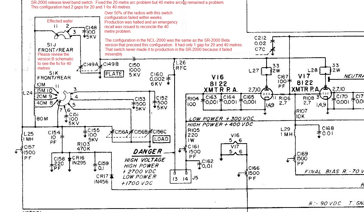
SR-2000 B level band switch configuration.
This switch configuration fixed both the 20 metre and 40 metre problems. Note the 80 and 40 Metre contacts have been jumpered together. Over the next 4 years only a hand full of switches failed.
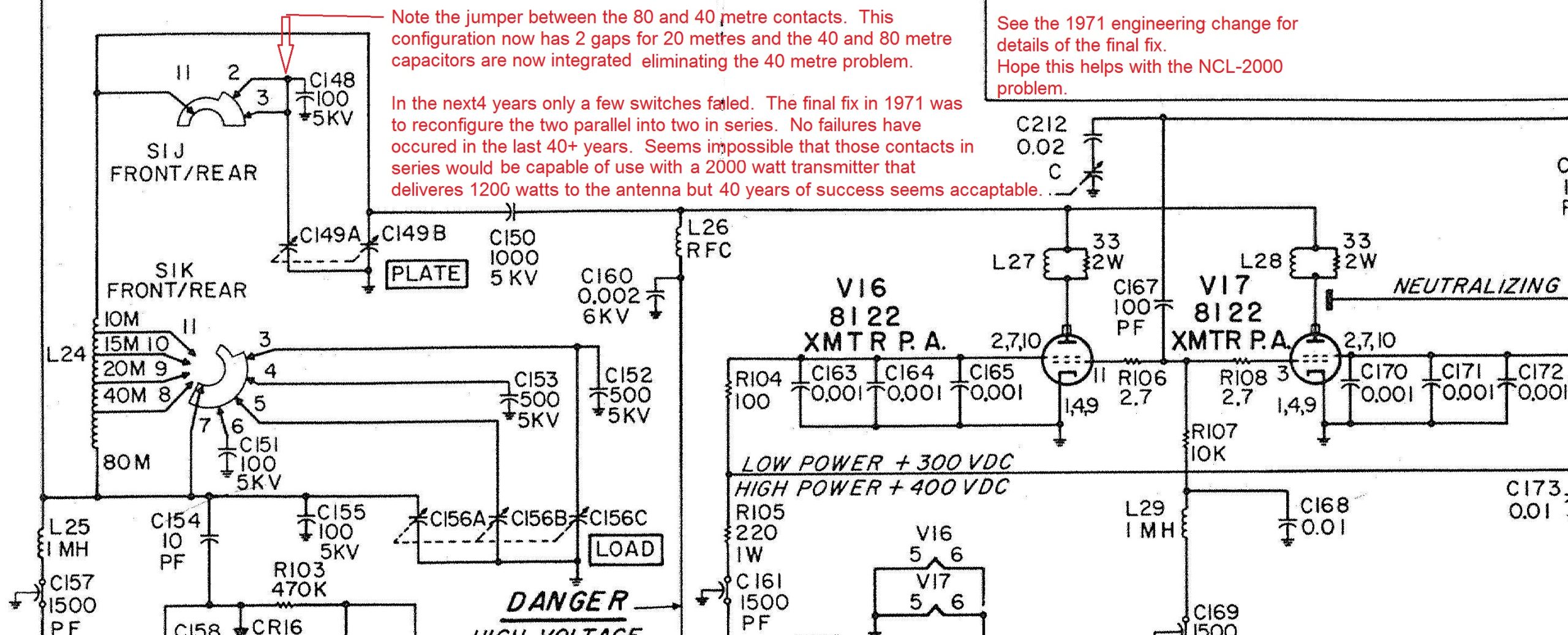
B level configuration:
Note the added gap when using the 20 Metre band. Is adding an extra gap to the NCL-2000 switch simply common sense?
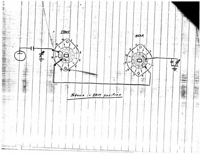
Final band switch configuration released in 1971
After 40 years of servicing and restoring the SR-2000 radio we have no evidence that any ever failed. This configuration should not be used on the NCL-2000 because it has not been regression tested with the NCl-2000. However the B level configuration above will eliminate the 40 metre problem and double the 20 Metre arc tollerance of the NCL-2000 configuration.
SR-2000 Final band switch configuration change notice. This is a four gap switch.
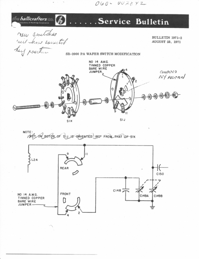
PHOTO OF NCL-2000 BURNED BAND SWITCH
Clearly shows the arcing started on the 40 Metre contact of the front wafer while operating on 20 Metres. Notice the scorching on the rear wafer that had nothing to do with the failure. This problem was never fixed and continues to plague NCL-2000 owners.
To determine the switch position at failure, rotate the front wafer rotor plate counter clockwise until the major damage from the arc on the rotor plate and hub line up with the destroyed 40 Metre contact. Yes, it was in the 20 Metre position. Note the view of the front rotor plate is of the back of it when facing the front on the radio. Now reassemble the switch mentally and you will find the damage on the rear plate to be across from the front wafer arcing. Also note the rear rotor plate is undamaged because it was nowhere near the arcing.
If most of these switch failures are a result of operator negligence, and the switch doesn't fail in the SR-2000, then the logical conclusion is that the operators of the SR-2000 are more careful than NCL-2000 owners, rediculous notion. No, the switch configuration in the NCL-2000 is flawed! Dump the notion that it's operator error and fix it. You'll be much happier.
Conclusion regarding the National NCL-2000 band switch
The band switch that was used in the NCL-2000 is the same OAK switch configuration as the Beta switch that Hallicrafters used in the pre-release SR-2000. It failed almost immediately when using the 20 or 40 Metre bands. Arcing could be provoked by increasing the line voltage to 122 or 244 volts and very lightly loading the finals (35 ma) of screen current in high power mode.
The changes that were made to the SR-2000 switch can be replicated to the NCL-2000 switch to eliminate the arcing risk on 40 metres and significantly reduce the risk on the 20 Metre band by more than 50%. There are newly manufactured switches available for the NCL-2000 but they are simply the same old switch configuration and further, they use silver plated copper. The original switch used coin silver or spring hard sterling silver not silver plated components. Doesn't make sense to install a switch that is certain to fail again.
The notion that the switch in the NCL-2000 is mainly attributable to operator error is ludicrous. Also ludicrous is the notion that the 10 pf capacitor used on the rear wafer between the 20 and 40 Metre contacts is somehow responsible for the arcing problem in the front switch. Had they used a shorting band switch like most designers, the problem with unintended resonant conditions in the unused coil section would not exist. You won't find this capacitor in the SR-2000 because it used a shorting switch in the rear wafer.
The shorting rear switch leaves the unused inductor segment so fractured that it can only resonate at well over 150 Mc. Too many octaves for any disturbances. The UNSHORTED band switch leaves a much larger coil segment that will be resonant at very close to the second harmonic of the fundamental frequency on at least one of the higher bands. What does this do? The transmitter does not pass harmonic muster. Does it cause the peak voltage in the tank to increase? NO, it reduces the Q of the coil slightly. The 10pf capacitor on the rear wafer is not responsible for the front wafer failing.
If you do nothing else, install the jumper or 50pf capacitor between the 40 and 80 Metre contacts on the front wafer. This will eliminate the risk of arcing on 40 Metres. If you use the 20 Metre band, configure the front rotor plate as per the B level switch update. It doubles the gap on the front switch. Do not use the 1971 update because it has not been regression tested using AM mode. The B level update is fool proof to install.
ADDED NOTE: Please review the New band switch configuration for SR-2000 and NCL-2000 service note for a fix for the front wafer on the SR-2000 and NCL-2000. The photo's are of the NCL-2000 switch integrating double gaps for both 80 and 40 Metres. The SR-2000 requires only three contacts; the 80 and 40 meter contacts are jumpered together not requiring the additional 80 Metre contacts.
Hope you found this interesting and helpful. Thanks for taking the time to review this material.
Kindest regards Jim K9AXN 10/07/2014