Page 1: RESTORING THE SR-2000
The restoration process for the SR-2000 includes a series of procedures that will ensure a stable, reliable, and trouble free radio. These procedures can be grouped in three categories, critical and absolutely necessary, should be done, and after production changes that improve the performance of the radio. I won’t say that it’s easy or quick but I can say that powering up a properly restored SR-2000 is a very special milestone. The following information will detail the various steps involved in the complete restoration of an SR-2000. If you find any step or information lacking clarity or details, please let me know and I’ll correct the inadequacy. Throughout the process, we will add links to photos of the pre and post work. I believe you will find the series interesting and useful as you pursue the process yourself.
Some steps will reference service notes and photos with links that will be added over time.
FINAL COMPARTMENT
To properly access the components in the final cage, the front panel and right side need to be removed.
Note: When removing the front panel, slide a card between the noise blanker pot and 500KHz index to prevent scratching it.
1. MUST: The metal screws in the HV connector and receptacle are replaced with nylon screws to prevent ticking in the receiver when high voltage is turned on which is caused by a corona discharge to the metal screw which is attached to the shell and chassis. See service note 003a and photo. The pre-production Plate and screen connectors were separate but changed to a single connector so the plate voltage could not be removed without the screen voltage.
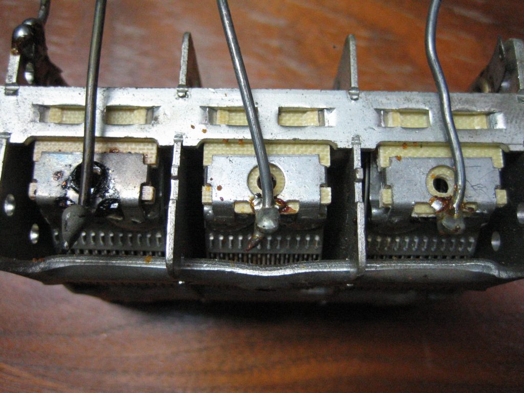
2. MUST: A jumper is attached to both stator connectors on the rear final loading capacitor section to load share when using the 10 meter band. Prevents over heating of the connector. See Service note 004a, photo of jumper, and photo of overheated capacitor.
Note: When soldering in the final compartment or high current connections, use Eutectic silver solder. It sets in a few large connections whereas non-Eutectic sets in a jillion small connections that fail over time much like carbon composition resistors where the resistance goes high as the granular connections burn off. Note the left 10 meter load cap connection has been over heated.
3. MUST: The receive coax running from the antenna relay is grounded at the receive input and must be insulated from ground in the final cage. The shield was stripped leaving some of the shield wire which can touch the chassis causing a ground loop and regeneration. Use a short piece of tape on the chassis to isolate it.
4. MUST: View RESTORE 6.jpg It has three arrows. #1 represents The added jumper on the 10 Metre loading capacitor. Arrow 2 circles the signal wires routed through the final cage. Use a dab of GOOP to hold them against the Chassis RESTORE 14 routed wires held.JPG
Verify that the wire routed from the bottom of the tank coil to the antenna relay is running on the opposite side of the tank coil from the signal wires.
5. MUST: All three segments of the loading capacitor should be high potted to 600 volts. I use a Heathkit IT-28 capacitor checker in Mica mode for leakeage. Turn the lights down and gradually increase the voltage while watching for sparks. The current is low enough that it won't damage the cap plates. This should be done after tightening the mounting screws.
6. SELECTION OF 8122 TUBES IS IMPORTANT: The selection of 8122 tubes for the SR-2000 is important. The SR-2000 was designed to deliver 1000 Watts to the antenna in SSB mode and use closely matched tubes. Closely matched tubes is not an option, it is an imperative when using multiple parallel tubes as suggested in the tube data sheets.
Even though a pair of 8122 tubes are matched, they may not fit the SR-2000 design profile. The 8122 is a beam type tube and beam type tubes universally have a range of plate current values that are approximately 2:1 (when used in class AB1 service). The plate current in an 8122 with 0 volts applied to the control grid, 400 volts to the screen, and 450 volts to the anode can range from 1000mA to 1800mA from tube to tube. This is not limited to the 8122, all beam type tubes have similar variations in plate current including the 6146, 6146A, and 6146B in AB1 mode. In AB2 or C mode, all can develop the same plate current because the control grid can be driven above 0 volts.
In AB1 mode the grid drive is limited to zero volts or less: Here is where the 2:1 issue emerges.
There are two data sheets for the RCA 8122; 1962 and 1966. The 1966 sheets were modified to accommodate designers when using SSB or class AB1 mode. They clearly define the minimum and maximum anode current that can be expected when the current is at maximum with the CG at 0 volts. Turn to page 4 of the 1966 sheets, Characteristics range values entry 8 note 6. It clearly states that the plate current will range from 1.0A to 1.8A, from tube to tube, when the grid voltage is zero (0).
Now read entry 3 note 3. It states that the grid voltage can vary from -8 to -19 volts to deliver .185A of plate current --- slightly higher than 2:1 --- this confirms the zero bias numbers above. What does all of this have to do with the SR-2000 and tube selection?
Calculate the power out for the lowest and highest current capable tube: The HV number will be the power supply 2700 volts - 200 volts for sag, - 400 volts for lowest plate voltage where max screen current occurs (2100 volts). Below are per tube calculations.
With 2100 volts using the low bias tubes, the max current 1.0 amps will occur when the control grid reaches 0 volts (Max for AB1 mode). The Power out = 1.0A x 2100V / 4 = 525 watts. Power in .636 x 1.0 x .5 =.318A x 2700 = 858 watts per tube. Dissipation 858 - 525 = 333 watts of plate dissipation.
With 2100V using the high bias tubes, the max current of 1.8 amps will occur when the control grid reaches 0 volts (Max for AB1 mode). The Power out = 1.8A x 2100V / 4 = 945 watts. Power in .636 x 1.8 x .5 = .5724 x 2700 = 1545 watts per tube. Dissipation 1545 - 945 = 600 watts of plate dissipation.
The 2:1 range for the 8122 can be translated to: A tube that you acquire can have a bias range from -20 volts to -44 volts that will result in 100mA of idle current in low power mode. Also, the neutralizing feedback required to stabilize the tubes will range somewhat proportionally, from low to high, along with the bias requirement. The neutralizing bridge sensor in the SR-2000 is a sliding tab. With the highest bias tubes, the tab will be impossibly close to the anode of the 8122 unless the bridge is redesigned, and the power out will far exceed the limits of the final design.
NOTE: This 2:1 range of plate current is not confined to the 8122, it will be found in any beam type tetrode. This will be explained in a follow on paper.
Orwin, the engineering manager and Stanford the designer of the SR-2000 negotiated with RCA to hand select 8122's that were in the second quadrant range for the SR-2000. The range was divided into 4 quadrants, later to be defined and published by Burle engineers.
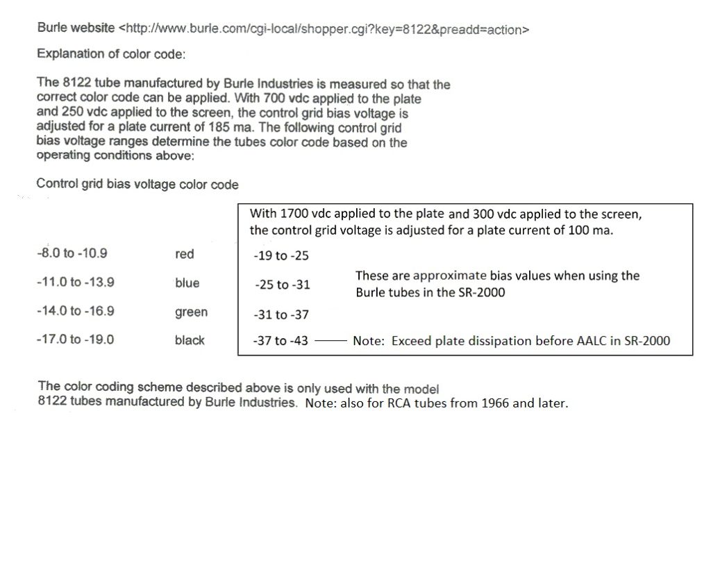
The RCA tubes first used and sold for replacements were equal to the Blue Burle tube. RCA and Burle tubes are made by the same people, however, there is no way without testing, to tell what you have with an RCA tube.
MORE TO BE ADDED HERE FOR THE FINAL COMPARTMENT
If you find anything above confusing, please let me know. This is not edited to death
CHASSIS WORK
1. MUST: Copper butter (Penetrox D) applied in a thin film to all of the screws in the chassis and between the final compartment walls and chassis to prevent chassis loops. This procedure will preempt many problems that are associated with inadvertent chassis loops. Specifically affected is the inability to neutralize the finals and intermittent unexplainable erratic behavior both in transmit and receive mode. See Service note 001a and photo.
2. MUST: Test every ground to chassis connection for < 1 ohm.
3. MUST: Each riveted joint where you find a star washer between the component and chassis (Tube socket, terminal strip, plate, etc.) apply Deoxit or Fader lube and tap the washer lightly on the side to reestablish the bite. Aluminum chassis radios with stainless steel rivets, when subjected to hostile temperature changes (-20 to +100 degrees) e.g. when stored in a garage or attic tend to incur oxidation in the rivet joint. A good indicator as to where the radio spent its life is how much resistance each of these joints display. Pay special attention to the bracket that holds the USB and LSB crystals. Check to see if the rivets have loosened and add a screw if there is any play. Use a self-tapping screw or you will have to go through the VFO enclosure. See Service note 006a
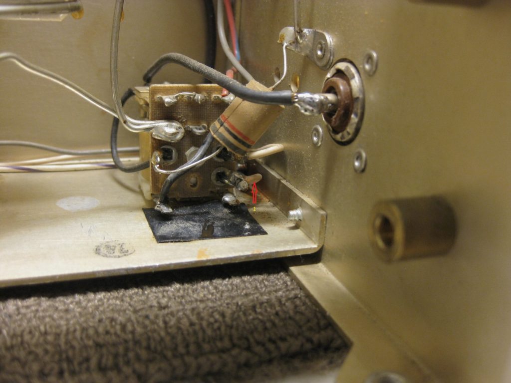
6. SHOULD DO: Add an IERC heat dispersing tube shield to the 6AQ5A. A good odometer for the SR-2000 is just how burnt and charred the relay is that is mounted next to the 6AQ5A. Note: The 6AQ5A runs at 425 degrees “F” and after the heat shield is add, will run about 350 degrees “F”. The 6AQ5A does not last long without heat dispersion and quickly loses conduction. The cathode voltage from the 6AQ5A is used to open the diode gates for the heterodyne oscillator signal to the first transmit mixer and balanced modulator to 6GX6A when in transmit mode. The range is 1.5V to 16V and will not be happy if the 16V degenerates to 14V or lower. See Service note 07a and Photo of 6AQ5A IERC
MORE IN PROCESS 1