30L1/30S1

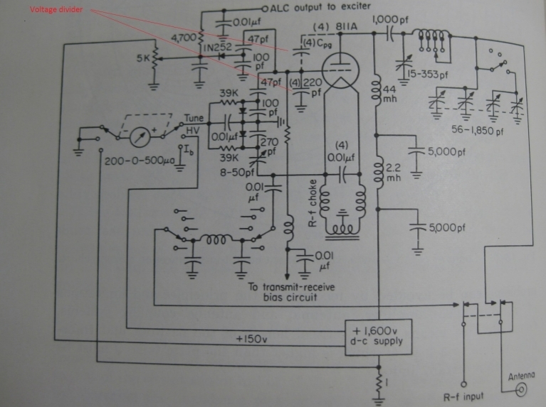
SCHEMATIC FOUND IN THESINGLE SIDEBAND PRINCIPALS AND CIRCUITS DESCRIBING THE 30L1 FEEDBACK VOLTAGE DIVIDER. THIS TEXT WAS WRITTEN BY COLLINS ENGINEERS.
NOTE: ALC as used in the 30L1 means Automatic Load Control ---not Automatic level control!
-
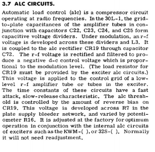
- The voltage divider as seen in note (4) above consists of the plate to grid inter electrode capacity (5pf) and the (220pf) capacitor that is added from grid to ground. The divider couples negative feedback to the grid that will be 1/40th of the plate peak to peak voltage swing. The photo above schematic is a more logical depiction of the 30L1 and can be found in (Sideband Principals And circuits) which was authored by the Collins engineers who participated in the 30L1 design review. It is also, described in the users manual 3.7
- The voltage divider provides a fraction of the plate voltage which is used to:
- Generate negative feedback to improve IMD and linearity.
- Effect neutralizing. At max plate PP 1300 volts, it applies -22 volts of negative feedback to the grid. This balances the -20 volts of destabilizing positive feedback from plate to cathode.
The voltage divider used in the 30L1 is the same divider that is used in the 30S1. - Input to the ALC/Automatic LEVEL Control rectifier line to control the exciter.
- Input to the ALC/Automatic LOAD Control comparator. Described below.
NOTE: There are a number of people who believe that the current that flows from cathode to grid during the conduction 1/2 cycle distorts the phase relationship of the drive but it has little if any effect. The 30L1 uses an RF choke to separate the DC current flow from the cathode to grid sinking the DC to ground leaving the ACvoltage from the divider to generate negative feed back. There is no AC reversing current flowing in the grid or plate chokes. The energy stored in the plate choke during the conduction half cycle is inserted during the non-conducting half cycle --- effect similar to push pull.
The above schematic is a more logical and easy to follow description of the 30L1 with the negative feedback components including the plate to grid capacity. The voltage divider NOTE (4) provides approximately 22 volts of negative feedback ( compression to the grids). The output of the voltage divider is used by the tune comparator to measure the plate PP voltage which is compared to the cathode drive voltage.
The upper leg of the comparator is driven by the voltage divider representing a fraction of the plate PP voltage and the bottom a fraction of the cathode voltage/drive. The top leg will develop a negative - voltage relative to the plate PP voltage and the bottom will develop a positive + voltage relative to the cathode drive. When they cancel the tune meter will read (0).
When the meter tune comparator is adjusted properly as per 4.7 in the manual, the the tune meter will dip to (0) with 300 ma of plate current: indicating resonance and proper load at max power out.
The tune logic enables you to tune the transmitter at reduced power 300 ma plate. Tuning the amplifier to max output power will be done once per operators manual 4.7 in order to calibrate the tune meter, NOT every time you change bands or antennas. Simply tune the transmitter for dip to (0) with 300ma of plate and the transmitter will be properly loaded and ready to operate at full output --- just increase the drive.
NOTE: The comparator was calibrated with the transmitter tuned and loaded to full power then the drive was reduced to 300 ma of plate current where the bridge was adjusted for dip to (0). You can now tune the amp at reduced power a very unique feature of the 30L1 design.
NOTE: If there are any modifications to the grid logic i.e. larger capacitors on the grids, directly grounding the grids, replacing the choke with something else, the comparator and tune meter will be useless.
The following is the explanation for the negative feedback voltage divider in the 30L1 manual.

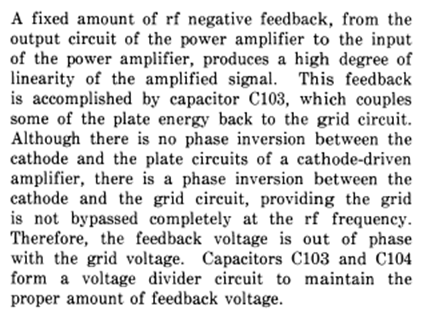
The following is the explanation for the 30S1 negative feedback voltage divider which has the same values as the 30L1.

Final comments:
Many think this negative feedback voltage divider doesn't work because of cathode to grid current in the 30L1. Interestingly, it requires nearly 30% more power to drive the amplifier with the divider installed than with directly grounded grids. The gain of the amp is significantly reduced.
What they overlooked is, it has an RF choke, not resistor from the grid to ground. The grid and plate RF chokes are subjected to VDC or DC pulse not AC. The current in these chokes does not reverse direction so it cannot be considered Alternating current. The 6.28xFxL equation is not accurate when using a plate or grid choke who's reactance is higher than the load impedance. The wl equation requires the voltage applied to the inductor be reversing, symmetrical, sine form, and current lagging 90 degrees.
The negative voltage fed back to the grid from the plate will be approximately -22 volts when the plate swing is at maximum, the destabilizing feedback from the plate to cathode will be approximately 20 volts which is positive feedback. It is only logical is you apply a 22 volt negative feedback signal to the grid it will handily neutralize the 20 volts of positive destabilizing feedback from plate to cathode.
The same voltage divider is used to successfully neutralize every transceiver that I know of as well as grid driven amplifiers, triode or tetrode.
There is a notion that the voltage divider cannot neutralize the GG amplifier because it does not neutralize the feedback at the cathode. The fact is it equalizes the feedback voltage between the grid and cathode. NOTE: The single ended Bruene neutralizing design used in nearly every transceiver or grid driven amplifier IS NOT DIRECT NEUTRALIZATION. The input tuned circuit is equalized and the entire feed back from plate to grid is used to generate negative feed back.
There was some talk of an analysis using the Nyquist equation. Short and to the point it's simple. It includes the gain of the tube, the feedback fraction, and phase of the feedback.
What is more complex is gathering the measurements that influence those measurements i.e. the gain of the tube varies with load.
The feedback from plate to grid is 180 degrees degenerative and would have to reverse by almost 180 degrees to be regenerative. Without reactance amplification i.e. a tuned circuit on the grid of a GG amp the voltage divider can only stabilize the amplifier and improve linearity.
Last, directly grounding the grids leaves them floating! Got your attention there!
A directly grounded grid will have .080uH of inductance and 15 ohms of inductive reactance at 29MHz and there's nothing that you can do to reduce it with a direct strap to ground.
Adding a 220pf capacitor to ground changes the character of the grid connection @ 30MHz from 15 ohms inductive for directly grounded grids to a 0 ohm series resonant short to ground. The grid will be capacitive at any frequency below series resonant. The directly grounded grid will always be inductive and always more inductive than the grid connection using the 220pf capacitor. This is how the brightest engineers of that era made the 811A an audio tube function in the RF region.
I have a question for the folks who say not so. Has anyone ever measured the frequency of oscillation in a GG amp that is guessed to have been caused by the lack of neutralization? I've never seen that measurement. A GG amp will oscillate at the tuned frequency if neutralization is the cause whereas a grid driven amp will oscillate just below the tuned frequency if neutralization is the cause.
NOTE: There is a tuning combination when using chokes whose reactance is close to the load impedance. When using the lowest band, under loading the amp can result in the load impedance increasing to a value higher than the choke reactance. The effect will be the seemingly inadequate capacity of the tune capacitor. The cause is some of the current in the choke has begun to reverse enabling that part of the current to participate in the output tuned circuit.
Think for yourself --- there are many theories based on superstition out there --- Ask for explanations using words.
This is not edited if anything is unclear please send a note.
Copyright James Liles 5/2017